
TLDR
- Head (H) is the energy per unit weight transferred by the pump to the liquid, expressed in meters of fluid column (m), overcoming elevation differences, pressures and head losses.
- It is calculated with the generalized Bernoulli equation: H = Hgeo + (Pm – Pa) / (ρ · g) + (vm² – va²) / (2 · g) + Hv, with g = 9.81 m/s².
- With the relation H (m) = P (bar) × 10.197 / γ, 3 bar corresponds to 30.6 m with water at 20 °C, 26.4 m with 33% HCl, 23.0 m with 30% caustic soda and 16.6 m with 98% sulfuric acid.
- At equal viscosity, the head in meters remains unchanged as the liquid density varies, while the shaft power absorbed (kW) increases in proportion to the specific weight.
- The CDR Pompe horizontal process series (ETN EVO, UTN, UCL, CCN, UTS EVO) cover heads up to 100 m and flow rates up to 300 m³/h at 2900 RPM.
Index
The head of a pump is one of the decisive design parameters to check before selecting and purchasing a pumping unit. Although it stems from a rigorous energy balance, this value answers a very practical question for anyone running a plant: will the selected pump be able to deliver the process fluid at the required flow rate to the point of use, overcoming elevations, back pressures and piping friction? Underestimating the head leads to insufficient flow rates or line stoppages, while excessive oversizing moves operation away from the best efficiency point (BEP), increasing energy consumption, vibration and wear.
At CDR Pompe we work every day with technical offices, process engineers and maintenance managers to select the right hydraulic configuration for the industrial, chemical and pharmaceutical sectors. In this guide we analyze the physical meaning of head, the complete calculation formula, quick conversion tables between pressure in bar and meters of liquid column for various chemical fluids, and practical criteria for reading data sheets correctly.
Let's understand what pump total head means.
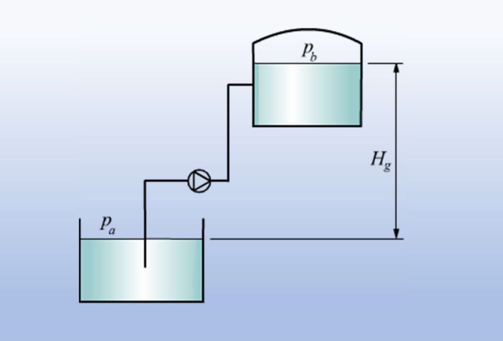
Head is the hydraulic quantity that expresses the maximum manometric height to which a pump is able to lift a fluid, and it is commonly measured in meters (m). In plant terms, it indicates the machine's ability to transfer the liquid from the suction section (the port through which the fluid enters the pump casing) to the discharge section (the outlet flange connected to the process piping), compensating for both the geometric elevation difference and all the distributed and localized hydraulic resistances along the circuit.
From a thermodynamic and fluid dynamic standpoint, head corresponds to the specific mechanical energy supplied by the impeller per unit weight of the pumped fluid (J/N, dimensionally equivalent to the meter). Unlike the pressure read on a pressure gauge, expressed in bar or Pascal, head in meters is a geometric and kinematic characteristic of the centrifugal pump that does not depend on the liquid density, provided the viscosity remains close to that of water.
Knowing exactly what head the circuit requires before you order lets you cross the system curve with the pump's performance curve and, at the same time, check the safety margin on the suction side, i.e. the available NPSH versus the required NPSH, avoiding destructive cavitation.
How to calculate head: formula and system components
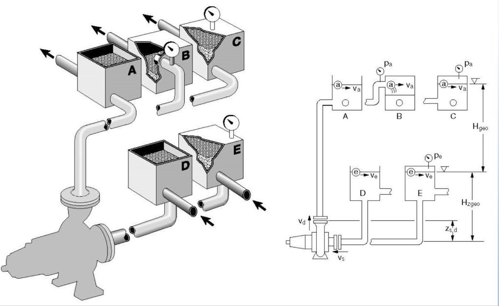
Applying the generalized Bernoulli equation for real fluids between the suction tank and the discharge tank, the total dynamic head (H) required of the system is calculated with the formula:
H = Hgeo + (Pm – Pa) / (ρ · g) + (vm² – va²) / (2 · g) + Hv
The table below summarizes all the terms of the equation, their consistent SI units of measurement, and the practical points to check during the on-site survey.
Table 1: components of the total head calculation formula
| Symbol | Physical quantity | Unit of measurement | Practical guidance for on-site measurement |
|---|---|---|---|
| H | Total manometric head | m | Total value to compare on the pump's flow rate-head (Q-H) curve at the required duty point. |
| Hgeo | Total geodetic head | m | Vertical elevation difference between the free surface at discharge and the free surface at suction (also to be added in the case of negative flooded suction). |
| Pm – Pa | Pressure difference between discharge and suction | Pa (N/m²) | Essential when transferring liquid from a tank under vacuum to a pressurized reactor or a filter press; if both tanks are open to the atmosphere, this term is zero. |
| ρ | Absolute density of the fluid at operating temperature | kg/m³ | For water at 20 °C it is approximately 1,000 kg/m³; for 98% sulfuric acid it rises to 1,840 kg/m³. It directly affects the pressure term and the absorbed power. |
| g | Gravitational acceleration | m/s² | Standard physical constant equal to 9.81 m/s². |
| vm, va | Average fluid velocity at discharge and at suction | m/s | The kinetic term (vm² – va²) / (2 · g) is often only a few tens of centimeters, but it must be checked if the pipe diameters differ significantly. |
| Hv | Total head losses of the circuit (suction + discharge) | m | Sum of the distributed friction losses along straight sections and the localized losses in bends, reducers, check valves, filters, heat exchangers and flow meters. |
On a centrifugal pump at constant rotational speed, head and flow rate are linked by an inverse relationship along the performance curve: as the volumetric flow rate (Q, expressed in m³/h) required by the system increases, the head developed by the pump progressively decreases, while the head losses Hv in the piping increase roughly with the square of the flow rate. The exact operating point always arises from the intersection of these two curves, as explained in more detail in our complete guide to pump sizing.
Quick calculation table: conversion between pressure (bar) and total head (meters) based on the fluid density
In industrial and chemical pumping, one of the most frequent mistakes is confusing differential gauge pressure (expressed in bar) with head expressed in meters of liquid column (m.l.c.). The practical conversion formula is:
H (m) = (P [bar] × 10.197) / γ
where γ indicates the relative specific weight (or density in kg/dm³) of the liquid at operating temperature. As the reference table below shows, for the same head in meters, a pump handling a high-density acid generates a much higher pressure in bar at the discharge flange than with water.
Table 2: quick bar / meter conversion for chemical and process fluids
| Pushed fluid (application example) | Specific gravity γ (kg/dm³) | Head 20 m (pressure in bar) | Head 40 m (pressure in bar) | Required pressure 3 bar (head in m) |
|---|---|---|---|---|
| Organic solvents and light hydrocarbons | 0.80 kg/dm³ | 1.57 bar | 3.14 bar | 38,2 m |
| Water industrial (20 °C) | 1.00 kg/dm³ | 1.96 bar | 3.92 bar | 30,6 m |
| Hydrochloric acid (33% HCl) | 1.16 kg/dm³ | 2.28 bar | 4.55 bar | 26,4 m |
| Caustic soda (30% NaOH) and brines | 1.33 kg/dm³ | 2.61 bar | 5.22 bar | 23,0 m |
| Concentrated sulfuric acid (H₂SO₄ at 98%) | 1.84 kg/dm³ | 3.61 bar | 7.22 bar | 16,6 m |
Technical note for sizing motors and magnetic couplings: while the head in meters (H) read on the performance curve remains unchanged as the fluid density varies (at the same viscosity), the shaft power absorbed (Pabs, in kW) increases in direct proportion to the specific weight γ. When pumping dense acids or concentrated solutions, it is therefore essential to correctly size both the electric motor and the torque the magnetic coupling can transmit.
Head in pump selection: comparing the CDR Pompe series
Before purchasing a magnetic drive pump or a mechanical seal pump, it is essential to check the rated and maximum head on the data sheet. Even pumps that look alike or have the same ISO 2858 standardized flanges may be fitted with different impeller diameters and motors, with very different hydraulic performance.
To guide designers and plant managers in preselection, the table below compares five flagship horizontal series designed and manufactured by CDR Pompe in Bollate (Milan), ordered by head and severity of service.
Table 3: quick comparison of CDR Pompe series by head, flow rate and application
| CDR Pompe series | Sealing technology | Wetted materials | Max head (2900 RPM) | Max flow rate (2900 RPM) | Fluid temperature range | Typical application |
|---|---|---|---|---|---|---|
| ETN EVO | magnetic drive | PP / ETFE | 35 m | 60 m³/h | -15 °C / +120 °C | Safe transfer of clean corrosive reagents in compact plants, water treatment and scrubbers. |
| UTN | Magnetic drive (ISO 2858) | PP / PVDF / PFA lining | 60 m | 150 m³/h | -50 °C / +160 °C | Fine chemicals, pharmaceutical and heavy-duty zero-emission processes with toxic or aggressive fluids. |
| UCL | Single or double mechanical seal (ISO 2858) | PP / PVDF / PFA lining | 75 m | 250 m³/h | -50 °C / +140 °C | Corrosive fluids, including dirty ones or those with small percentages of suspended solids. |
| CCN | mechanical seal | Heavy-duty PP / PVDF construction | 100 m | 300 m³/h | -15 °C / +90 °C | High heads and large flow rates in basic chemicals, pickling, electroplating and industrial wastewater treatment. |
| UTS EVO | Magnetic drive (ISO 2858) | AISI 316 stainless steel / special alloys | 100 m | 300 m³/h | -140 °C / +300 °C | High temperatures, thermal oil fluids, flammable solvents in ATEX zones and petrochemical plants. |
Our advice always remains the same: never buy a pump without a certified performance curve and a transparent data sheet. Since 1950, at CDR Pompe we have designed and tested process pumps for corrosive, toxic and hazardous liquids, supporting customers in over 50 countries with precise selection at the real duty point. If you are sizing a new line or considering replacing an existing pump, you can contact our Technical Office by sending the flow rate, estimated head, chemical nature and temperature of the fluid.
Frequently Asked Questions
What is the power total head of a centrifugal pump and in what unit of measurement is it expressed?
Head is the maximum height to which a pump can lift a fluid, commonly expressed in meters (m). It indicates the energy per unit of weight supplied by the impeller to overcome the geodetic elevation difference, any pressure difference between the tanks, and all friction head losses along the suction and discharge piping.
What is the correct formula for calculating pump head?
The total head H (in meters) is calculated with the generalized Bernoulli equation: H = Hgeo + (Pm – Pa) / (ρ · g) + (vm² – va²) / (2 · g) + Hv, where Hgeo is the geodetic elevation difference, Pm – Pa the pressure difference between discharge and suction, ρ the liquid density in kg/m³, g the gravitational acceleration (9.81 m/s²), vm and va the fluid velocities, and Hv the total head losses of the circuit.
How is pressure converted into meters total head in bars for fluids other than water?
The formula H (m) = (P [bar] × 10.197) / γ applies, where γ is the specific weight of the fluid in kg/dm³. To obtain a differential pressure of 3 bar, you need 30.6 m of head with water at 20 °C (γ = 1.00), 38.2 m with light solvents (γ = 0.80), 26.4 m with 33% hydrochloric acid (γ = 1.16), 23.0 m with 30% caustic soda (γ = 1.33) and 16.6 m with 98% sulfuric acid (γ = 1.84).
What is the relationship between head and flow rate in a centrifugal pump?
Along the performance curve of a centrifugal pump at constant speed, head and flow rate vary inversely: as the volumetric flow rate (m³/h) delivered increases, the available head in meters decreases. The actual duty point of the machine lies at the intersection of the pump curve and the system resistance curve.
Do head and absorbed power change when the fluid density changes?
At the same viscosity, the head in meters read on the performance curve of a centrifugal pump remains identical whatever the density of the liquid. By contrast, both the discharge pressure measured in bar and the shaft power absorbed in kW increase in direct proportion to the specific weight, making it necessary to check the electric motor and the magnetic coupling on heavy fluids.
What head do CDR Pompe process pumps reach for chemical fluids?
At 2900 RPM, the CDR Pompe horizontal series cover heads up to 35 m with the compact ETN EVO magnetic drive pumps, up to 60 m with the ISO 2858 lined UTN series, up to 75 m with the UCL series lined mechanical seal pumps and up to 100 m (with flow rates up to 300 m³/h) both in the CCN series thermoplastic versions and in the UTS EVO series magnetic drive pumps in stainless steel and special alloys.
Where can I find the head value before buying an industrial pump?
The rated head value and the entire flow rate-head performance curve are given in the official data sheet of each model and are verified by the manufacturer at the technical quotation stage based on the duty point provided by the customer.


